![Logo_Variation_7_copy-removebg-preview.png](https://static.wixstatic.com/media/c276ad_9f3d1ae10cc84b09a92a4ad007681d22~mv2.png/v1/fill/w_177,h_116,al_c,q_85,usm_0.66_1.00_0.01,enc_avif,quality_auto/Logo_Variation_7_copy-removebg-preview.png)
Installation Instructions
Need more help? Contact us.
These installation instructions are a guideline. Uzarski Designs assumes no responsibility for improper disassembly/reassembly of your equipment.
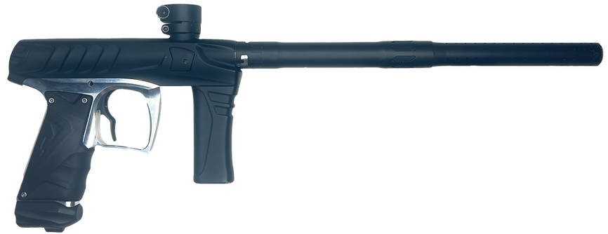
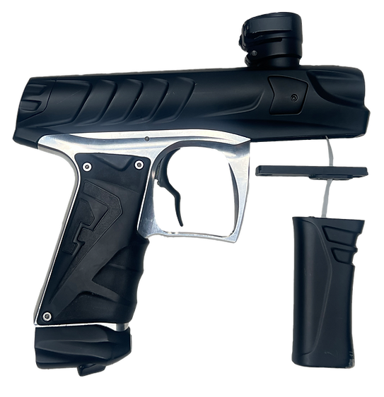
1. Empty the marker and gather components
Check there are no paintballs in the feedneck.
![Step 1 - Marker_edited.png](https://static.wixstatic.com/media/c276ad_7190c725d6134747875ac9ca5d7279fa~mv2.png/v1/crop/x_301,y_1171,w_2481,h_956/fill/w_866,h_334,al_c,q_85,usm_0.66_1.00_0.01,enc_avif,quality_auto/Step%201%20-%20Marker_edited.png)
Grip Tip: Don't put the rubber over-grip on the core until everything is installed. It's difficult to remove over-grip when not installed on the marker.
![grip.png](https://static.wixstatic.com/media/c276ad_4847b42b5ac146faa3399942bc54c960~mv2.png/v1/fill/w_26,h_26,al_c,q_85,usm_0.66_1.00_0.01,enc_avif,quality_auto/grip.png)
De-gas the marker by turning the cam drive knob counter-clockwise. Remove the air tank.
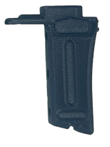
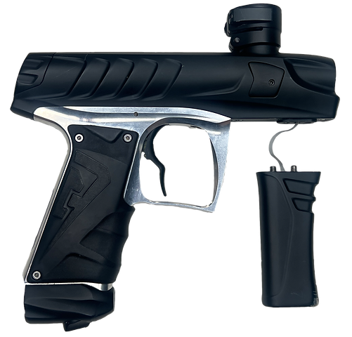
Gather the rubber over-grip
![Step 1 - Rubber foregrip_edited.png](https://static.wixstatic.com/media/c276ad_afa62335431e4cec8043100cccef0287~mv2.png/v1/crop/x_1195,y_751,w_139,h_238/fill/w_125,h_213,al_c,q_85,usm_0.66_1.00_0.01,enc_avif,quality_auto/Step%201%20-%20Rubber%20foregrip_edited.png)
![Step 1 - Forgrip Base_edited.png](https://static.wixstatic.com/media/c276ad_67805306dca843a5b5b9466adbab3293~mv2.png/v1/crop/x_0,y_1,w_381,h_506/fill/w_159,h_213,al_c,q_85,usm_0.66_1.00_0.01,enc_avif,quality_auto/Step%201%20-%20Forgrip%20Base_edited.png)
+
![Step 1 - Blue Hex Key_edited.png](https://static.wixstatic.com/media/c276ad_881efa4ef7794b0f8e13bdee31fe170a~mv2.png/v1/fill/w_99,h_247,al_c,q_85,usm_0.66_1.00_0.01,enc_avif,quality_auto/Step%201%20-%20Blue%20Hex%20Key_edited.png)
![Step 1 - Red Hex Key_edited_edited.png](https://static.wixstatic.com/media/c276ad_e92332ee5935436091d4e77d3768da57~mv2.png/v1/fill/w_81,h_168,al_c,q_85,usm_0.66_1.00_0.01,enc_avif,quality_auto/Step%201%20-%20Red%20Hex%20Key_edited_edited.png)
![Step 1 - Yellow Hex Key_edited.png](https://static.wixstatic.com/media/c276ad_2502cf4dc6f84b8186427f47743044ae~mv2.png/v1/crop/x_0,y_13,w_65,h_107/fill/w_68,h_112,al_c,lg_1,q_85,enc_avif,quality_auto/Step%201%20-%20Yellow%20Hex%20Key_edited.png)
![Step 1 - Screws_edited.png](https://static.wixstatic.com/media/c276ad_cc8d8273ec6d45c09d49a12c077ee695~mv2.png/v1/fill/w_63,h_60,al_c,q_85,usm_0.66_1.00_0.01,enc_avif,quality_auto/Step%201%20-%20Screws_edited.png)
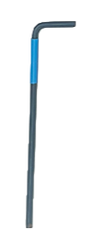
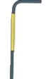
Complimentary tools and hardware
Core
+
![Step 1 - LiPo Battery_edited_edited.png](https://static.wixstatic.com/media/c276ad_b3b36f1c4d4f408582b4c82972f6000c~mv2.png/v1/fill/w_133,h_195,al_c,lg_1,q_85,enc_avif,quality_auto/Step%201%20-%20LiPo%20Battery_edited_edited.png)
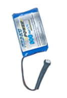
The Field One LiPo battery
(Sold separately)
2. Remove the battery door and AA batteries
![Step 2_edited.png](https://static.wixstatic.com/media/c276ad_31dcb5c14ae749db9a9dd18cf9fa542a~mv2.png/v1/fill/w_250,h_185,al_c,q_85,usm_0.66_1.00_0.01,enc_avif,quality_auto/Step%202_edited.png)
Check the direction of the arrow on the battery door.
![grip.png](https://static.wixstatic.com/media/c276ad_4847b42b5ac146faa3399942bc54c960~mv2.png/v1/fill/w_26,h_26,al_c,q_85,usm_0.66_1.00_0.01,enc_avif,quality_auto/grip.png)
Grip Tip: The battery door release screw only needs to be rotated ~¼ turn before the battery door pops out. Rotate the screw in the direction shown on the battery door.
Use a 1/8” hex key to rotate the battery door’s release screw ~¼ turn. The door should pop out.
![Step 2.3 - Blue Hex Key and Battery Door.png](https://static.wixstatic.com/media/c276ad_153e9b174c3e49a9ae8948cf9e8e5101~mv2.png/v1/crop/x_2533,y_2160,w_393,h_960/fill/w_130,h_318,al_c,q_85,usm_0.66_1.00_0.01,enc_avif,quality_auto/Step%202_3%20-%20Blue%20Hex%20Key%20and%20Battery%20Door.png)
![Step 2.2 - Battery.png](https://static.wixstatic.com/media/c276ad_b14fdb8669b24213b87576156b9bd443~mv2.png/v1/crop/x_2573,y_2660,w_360,h_587/fill/w_61,h_99,al_c,q_85,usm_0.66_1.00_0.01,enc_avif,quality_auto/Step%202_2%20-%20Battery.png)
Remove the battery door and the AA batteries.
![Step 2.2 - Marker.png](https://static.wixstatic.com/media/c276ad_05ae36decbab48658bd86e34b725cca7~mv2.png/v1/crop/x_980,y_993,w_2040,h_2073/fill/w_423,h_430,al_c,q_85,usm_0.66_1.00_0.01,enc_avif,quality_auto/Step%202_2%20-%20Marker.png)
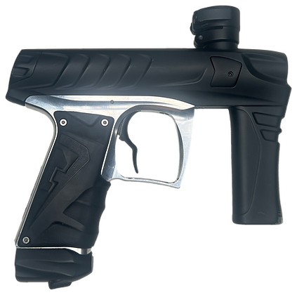
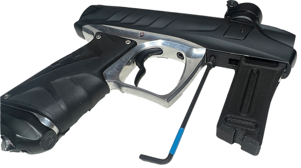
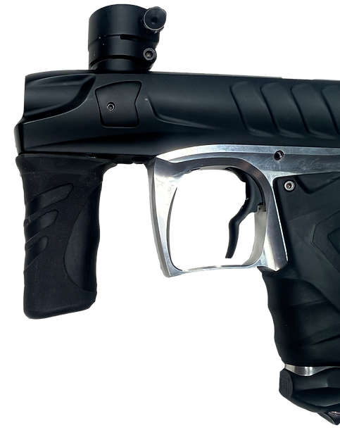
3. Disconnect the foregrip and reversal plate
Hold the foregrip in place. Use a 1/8” hex key to fully loosen the screws within each of the two springs inside the foregrip.
Grip Tip: When the foregrip core screws are removed, the grip will be connected to the frame with the battery harness. Don't put tension on the harness.
![Step 3_edited.png](https://static.wixstatic.com/media/c276ad_dd6e46b819d8404c818f4406f3dfa704~mv2.png/v1/fill/w_142,h_306,al_c,q_85,usm_0.66_1.00_0.01,enc_avif,quality_auto/Step%203_edited.png)
![grip.png](https://static.wixstatic.com/media/c276ad_4847b42b5ac146faa3399942bc54c960~mv2.png/v1/fill/w_26,h_26,al_c,q_85,usm_0.66_1.00_0.01,enc_avif,quality_auto/grip.png)
![Step 3.1.png](https://static.wixstatic.com/media/c276ad_e212f8d5ce11426cac138becf3eb23ec~mv2.png/v1/crop/x_434,y_1000,w_2654,h_2010/fill/w_544,h_412,al_c,q_85,usm_0.66_1.00_0.01,enc_avif,quality_auto/Step%203_1.png)
![Step 3.2.png](https://static.wixstatic.com/media/c276ad_a5e00335736c49df93984ef11443e89e~mv2.png/v1/crop/x_887,y_1013,w_2067,h_1980/fill/w_501,h_480,al_c,q_85,usm_0.66_1.00_0.01,enc_avif,quality_auto/Step%203_2.png)
The screws will stay retained within the foregrip. Carefully separate the foregrip so there's no tension on the battery harness.
![Step 3.3.png](https://static.wixstatic.com/media/c276ad_fc41b65f56574d3ab3468748299e43ce~mv2.png/v1/crop/x_0,y_853,w_3473,h_2107/fill/w_715,h_434,al_c,q_85,usm_0.66_1.00_0.01,enc_avif,quality_auto/Step%203_3.png)
Grip Tip: Place the marker on a flat surface so the foregrip does not put tension on the battery harness.
![grip.png](https://static.wixstatic.com/media/c276ad_4847b42b5ac146faa3399942bc54c960~mv2.png/v1/fill/w_26,h_26,al_c,q_85,usm_0.66_1.00_0.01,enc_avif,quality_auto/grip.png)
Use a 1/8” hex key to remove the two screws retaining the reversal plate.
![Step 3.4.png](https://static.wixstatic.com/media/c276ad_8da53ace7f974337ba1f6e6ee99c0c42~mv2.png/v1/crop/x_1013,y_933,w_2127,h_2200/fill/w_543,h_562,al_c,q_85,usm_0.66_1.00_0.01,enc_avif,quality_auto/Step%203_4.png)
Carefully separate the reversal plate from the body. Check there is no tension on the battery harness.
4. Disconnect the battery harness
![Step-4.5.gif](https://static.wixstatic.com/media/c276ad_a93abbc55cda47019643ac23f47b548f~mv2.gif/v1/fill/w_242,h_430,al_c,usm_0.66_1.00_0.01,pstr/Step-4_5_gif.gif)
Detach the battery harness from the bridge board by carefully pulling it out.
Set the foregrip, reversal plate, and battery harness to the side.
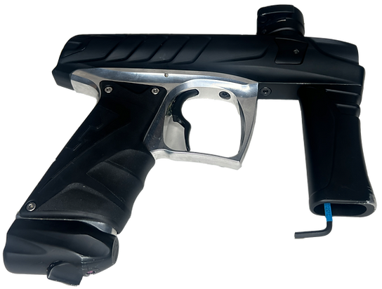
5. Install the lightweight foregrip
![Step 5_edited.png](https://static.wixstatic.com/media/c276ad_a232dca889ff47e2bfe0615e6c119cae~mv2.png/v1/crop/x_10,y_0,w_1607,h_1602/fill/w_528,h_526,al_c,q_85,usm_0.66_1.00_0.01,enc_avif,quality_auto/Step%205_edited.png)
![Step 5 Foregrip_edited.png](https://static.wixstatic.com/media/c276ad_cdf7d87c4a3340ffba9f0cec5b0be822~mv2.png/v1/crop/x_0,y_21,w_508,h_721/fill/w_156,h_221,al_c,q_85,usm_0.66_1.00_0.01,enc_avif,quality_auto/Step%205%20Foregrip_edited.png)
Align the core to the body where the reversal plate was installed.
![](https://static.wixstatic.com/media/c276ad_7fe9bf021bbb45dca228024ecc136bb6~mv2.png/v1/crop/x_965,y_703,w_2970,h_2277/fill/w_556,h_426,al_c,q_85,usm_0.66_1.00_0.01,enc_avif,quality_auto/c276ad_7fe9bf021bbb45dca228024ecc136bb6~mv2.png)
Install the forward screw and tighten it with a 5/32” hex key.
![Step 5_edited_edited.png](https://static.wixstatic.com/media/c276ad_dce7168c232e4e88af9ff0bb1bf6e2ed~mv2.png/v1/fill/w_595,h_332,al_c,q_85,usm_0.66_1.00_0.01,enc_avif,quality_auto/Step%205_edited_edited.png)
Install the rear screw and tighten it with a 1/8” hex key.
![Step 5_edited.png](https://static.wixstatic.com/media/c276ad_8eccdba5609344fe9d2b851a3dfbf0f8~mv2.png/v1/crop/x_0,y_23,w_1511,h_1501/fill/w_561,h_557,al_c,q_85,usm_0.66_1.00_0.01,enc_avif,quality_auto/Step%205_edited.png)
Slide the rubber over-grip over the core until the upper tabs are about to engage.
Tuck the side tabs into the core and install the rubber over-grip the rest of the way.
![Step 5_edited_edited.png](https://static.wixstatic.com/media/c276ad_395cd768cb504d409ff4953dae5d81c3~mv2.png/v1/crop/x_20,y_0,w_1658,h_2086/fill/w_483,h_608,al_c,q_85,usm_0.66_1.00_0.01,enc_avif,quality_auto/Step%205_edited_edited.png)
Grip Tip: Press firmly all around the grip to ensure the over-grip is sealed to the core.
![grip.png](https://static.wixstatic.com/media/c276ad_4847b42b5ac146faa3399942bc54c960~mv2.png/v1/fill/w_26,h_26,al_c,q_85,usm_0.66_1.00_0.01,enc_avif,quality_auto/grip.png)
Press the rear tab into the core until the rear of the grip sits flush to the marker.
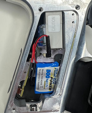
6. Install the LiPo rechargeable battery
![Step 6.png](https://static.wixstatic.com/media/c276ad_6bbfe20995654f258db1367ca61f7815~mv2.png/v1/crop/x_1842,y_497,w_2158,h_2386/fill/w_477,h_527,al_c,q_85,usm_0.66_1.00_0.01,enc_avif,quality_auto/Step%206.png)
Orient the marker so the barrel is to the right. Use a 5/64” hex key to remove the three grip frame screws.
Open the grip panel.
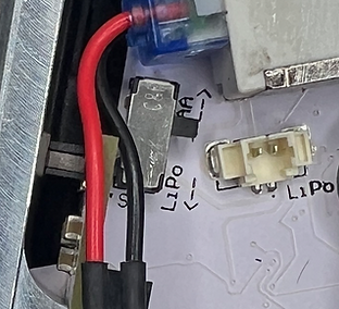
Toggle the power selector switch to “LiPo”.
![Step 6.1.png](https://static.wixstatic.com/media/c276ad_0cedbf5d5c924554b8478e7d5c80c78c~mv2.png/v1/crop/x_1818,y_1210,w_694,h_631/fill/w_312,h_284,al_c,q_85,usm_0.66_1.00_0.01,enc_avif,quality_auto/Step%206_1.png)
![IMG_7541 (1)_edited_edited.jpg](https://static.wixstatic.com/media/c276ad_8a7b35eb59ce44ffb573a746f452d2d1~mv2.jpg/v1/fill/w_297,h_363,al_c,q_80,usm_0.66_1.00_0.01,enc_avif,quality_auto/IMG_7541%20(1)_edited_edited.jpg)
Connect the LiPo battery to the board’s connector labeled “LiPo”.
Close the grip panel.
Install and tighten the three grip frame screws with a 5/64” hex key.